Proposed Smart Data Acquisition Device for Autonomous Cooperation
index >> Proposed PCB electronics hardware for Live Data Acquisition
[*] Structural smart, carbon fiber-based, composites can be utilized for the automation of Structural Health Monitoring and structural self-repair [19][20]. Connected with hardware electronics capable of running more complex tasks beyond the simple ability of automatic sensing and calibration enhances further autonomous sensing ability of this type of structural composite materials. For this research work, was designed in KiCad and prototyped hardware electronics (figure 4) capable of local edge server computing tasks such as machine learning and artificial intelligence modeling of live data, collected onboard plus live data being relayed over the structural monitoring network. It also has the ability to store data locally and perform autonomous real-time decision-making in regards to structural health & serviceability. The proposed hardware electronics (figures 4, 5) are powered by Dual Xtensa LX7 Core Processors clocked to a maximum of 240MHz with a maximum of 1Gb of NOR Flash storage and a maximum of 1Gb of PSRAM according to specific structural monitoring needs. Network connectivity on the hardware is possible through a CAN V2.0B, a TSSOP-20 MCP2515 IC from Microchip, connected with a 1.0 Mbit high-speed transceiver, a SOP-8 TJA1050 from Philips, fully compatible with ISO 11898, able to operate at low DC voltages. CAN connectivity enable simple installation without requiring changes or downtime on the structural monitoring network. Is a fully decentralized network architecture where multiple devices can be configured to perform server tasks on the network, this is important when considering damage to any electronic components that require replacement, without affecting the serviceability of the structure. Hardware electronics also include connectivity using ISM bands available at 2.4GHz with the purpose of enabling connection and providing useful data about the structure, to any unknown mobile device passing nearby.


Figure 9.1 - SDAD assembled into a waterproof acrylic case and ready to be installed on top of a cylindrical specimen
The hardware has cryptographic capabilities, a SOIC-8 ATSHA204A IC from Microchip, to provide secure data communications (SHA-256), and more importantly, to provide unique sensor data measurements to the network in real-time. This is a mandatory component that serves the purpose of delivering a unique hash signature on any individual sensor data measurements made, including from the smart structural composites it connects, while providing information about the relative location of live (time) sensor measurements and also the electronics itself that did the measurements. Onboard hardware sensor components include a MEMS sensor, the LSM6DS3 from ST Microelectronics, for 3-axis digital accelerometers and 3-axis digital gyroscope measurements. It has an output data rate (ODR) of up to 1.6 kHz and 8 Kbyte FIFO with dynamic allocation of significant data. A CMOS sensor, the SHT3.x from Sensirion, fully calibrated, linearized, and temperature-compensated digital measurements with accuracies of ±1.5 % RH for humidity measurements and ±0.2°C for temperature measurements. These sensors allow hardware electronics to do self-compensation and self-calibration on measurements made on any of the smart structural composites connected. To power this hardware electronics is an 85-220V AC to 5V 1000mA DC rectifier managed by a high-performance primary sensing regulator (PSR) and monolithic switch power controller, the SOP-5 HT2812H from HotChip. This is the main provider of energy to the electronics and also to the CAN BUS Network, set up to operate at ±5V DC. Power management on the electronics includes safety fuses, two AC fuses, and one DC fuse for overvoltage and overcurrent protection. For emergency situations, electronics can be powered by any 4.2V DC Lithium Polymer Battery connected to a constant frequency current 5.0V 2000mA DC converter, the SOT23-6
[*] The text below is from a previously published paper and requires rewriting to avoid "plagiarism"
Table 9.1 - Hardware Specifications of the Smart Data Acquisition Device Prototyped
-
QFN 56 Dual Xtensa LX7 Core Processors running up to 240MHz
- RISC V ultra-low power co-processor
- 512Kb RAM (PSRAM max 1 Gb);
- 16Mb SOIC 8 NOR SPI Flash Memory (max 1Gb);
- 2.4GHz ISM wireless connectivity;
- Up to 118 12bit ADC Multiplexed DAQ channels;
-
Onboard Storage:
- 2x SPI Flash WSON-8 Chips for local storage upwards of 4Gbytes.
-
Authentication & Security:
- SOIC-8 ATSHA204A SHA-256 high-security hardware authentication IC for secure and unique experimental data exchange
-
Power management
- DFN-6 AUR9718/ST1S09 high efficiency step-down 3.3V 1.5A DC converter;
- CN3065 4.2V Lipo Battery Management System
- USB-C connection for 5.0V 1.0A power supply from any power charger found on smartphones or tablets.
- JST SH 2 pin 1.0mm for specific power supply applications (3.3V to 5.0V 1.0A DC)
-
Onboard sensors:
- DFN-8 AHT20; temperature sensor with a precision of 0.1 C;
- DFN-8 AHT20 humidity sensor;
- LGA-14 LSM6DS3 a 6-axis accelerometer and gyroscope;
- TEMT6000 Luminosity Sensor;
- SOT 23-3 reference voltage sensor;
- BMP280 Atmospheric pressure sensor;
- ENS120 TVOC sensor;
-
Connectivity
- 2.4GHz WIFI
- Bluetooth & BLE
- USB-C serial communication
- USB-C to Serial UART communication
-
External connectivity for up to 118 sensors 12 to 16bit with onboard voltage reference analyzer with temperature compensation and automatic ADC calibration:
- 1x I2C pin terminal connector (4 pin)
- 1x ADC 16-bit analog terminal connector (3-pin)
- 1x ADC Ohmmeter connection with 16-bit with scale selection via firmware code
-
Display
- 1.69" TFT LCD Display with a resolution of 320x280 px
-
Channel 1 & 2
- Connector Power: MCU IO ??
- Voltage Reference: MCU IO ??
-
Channel 1 ADC: MCU IO ??
- 3 pins JST SH 1.0mm connector: 3.31V DC, GND, ADC
-
Channel 2 I2C: MCU IO 8 (SDA); MCU IO 9 (SCK)
- 4 pins JST SH 1.0mm connector: SDA, SCK, 3.31V DC, GND
-
Power Source
- Battery Level: MCU IO ??
- 2x 2-pin battery JST SH 1.0mm connector with a Max input 5.0V DC
- USB-C connector: standard 5.0V DC USB-C connector, max 1A

Figure 9.2 – hardware electronics design layout. To the Left: top side of the hardware electronics; to the right: bottom side of the hardware electronics
In summary, this hardware is capable of performing the following computing tasks:
- connect to all kinds of 3.3V digital sensors;
- connect to all kinds of sensors compatible with the I2C protocol. (max 118 sensors simultaneously)
- measure voltage in the range of [0;3.3V]
- measure electrical resistance [0; 10^6] Ohm
- do temperature and humidity compensation on all measurements
- has a voltage reference sensor for improved accuracy on ADC measurements
- has a motion sensor to know if anyone moved a specimen during an experiment
- can be powered using 4.2V LiPo batteries
PCB design was made to fit any universal ABS box with dimensions of 54x46mm. In Figure 5 the proposed PCB is installed on an OEM IP55 water-resistant universal ABS box.
With the proposed Swarm model is possible to set up many Smart Data Acquisition Devices (SDAD) to collaborate autonomously and link individual measurements on each individual specimen, together, by sharing individual unique data fingerprint data IDs (UDFID) with each other stored redundantly, across the different local databases.
DAQ Cooperation in the same batch and the same experiment
DAQ cooperation in the same experimental setup is presented schematically in figure 1 above. Each specimen is instrumented and connected to an individual smart data acquisition device. On each sensor data measurement, each individual smart DAQ requests a new UDFID to all SDADs in the same experimental setup. It sends the newly generated data record to each and in return receives the corresponding UDFID and appends it. The proposed Swarm model has a time dependency associated with this method of performing local data validation and authentication. By requesting a UDFID to all SDADs in the same experimental setup, is possible to establish a direct data record relation among all devices by time proximity and also by global environmental variables proximity obtained from individual onboard sensor measurements (temperature, humidity, and luminosity). This way all experimental data produced during an experiment is automatically linked using a blockchain-like approach.

This blockchain-like logic includes not only the UDFID of the previous data measurement but also all UDFIDs generated on all other specimens in the same experimental setup. An example, let's say a researcher has set up 3 specimens for a round of testing, each scheduled sensor data measured, on each of the 3 specimens, will include the sensor data itself with its unique fingerprint ID, and also all fingerprint IDs from the other 2 specimens generated from the current time-indexed measurement. In total, for this particular example, with only 3 specimens, any sensor data, at any given time, will hold 4 UDFIDs on every individual data record. For the case of a setup with 5 specimens, each data record will hold 6 UDFID.
This way recording experimental data has an advantage over traditional experimental data acquisition setups. The ability to upload experimental data in real-time, to a remote data repository, assists remote researcher teams to do data validation with the lowest latency only limited by technology constraints and network bandwidth usage at any given time.
DAQ Cooperation in the same batch and different experiments
Is also possible to link experimental data blocks collected from the same batch of specimens across different experimental setups: Setup to start on the same date and time Setup to start at different dates and times and with the same measurement interval For such cases, the recording of individual "experimental data blocks" will include a time-dependent index key, linking individual sensor data measurements, and also include all fingerprint IDs for the corresponding index key from each specimen across the different experimental setups. For a better understanding of what is previously said, consider 2 different experiments with the same batch of 5 specimens each. For this particular setup, each sensor data measurement is stored on its individual "data block" with its individual unique fingerprint ID will also include all unique fingerprint IDs from all specimens across the 2 experiments, a total of 10 fingerprint IDs. This kind of data validation logic, using data redundancy and time-aware experimental data measurements, allows a researcher to present dataset files where sensor data is linked to any and all other experiments previously set up and linked to do data measurements. This increases the trustworthiness of data stored in a public data repository while at the same time allowing remote researchers to program and automate experimental data linkage. For instance in an Excel workbook or in a Python script.
DAQ Cooperation with different batches in the same project
It is also possible to link experimental data blocks collected from different batches of specimens across different experimental setups. In all similar, if not equal, to what was described previously.
DAQ Cooperation with different research projects
Finally, this smart DAQ, allows the linkage of individual sensor data measurements across different research projects, whether happening in the same physical laboratory or at different laboratory locations. The same principles previously stated are applied. Individual Smart DAQs are set up and configured to exchange data autonomously, with the purpose of generating, storing, managing, and exchanging unique data fingerprint IDs from the different experimental data sources.
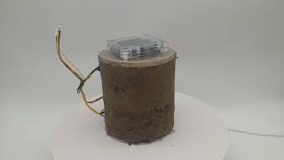
Video 1 – 360° view preliminary setup instrumentation of a "rammed earth" specimen with a 12-bit Smart DAQ
Swarm Intelligence << Proposed PCB electronics hardware for Live Data Acquisition >> Conclusions
🟢 Fully tested and working
A green circle means the hardware electronics or the programming code was fully tested, each of its functionalities and capabilities. And it can be installed in a vehicle. Keep in mind this does not mean errors won't happen. As in everything related to electronics and software, there are revisions and updates. This open hardware is no different.
💯 Fully tested & working, no improvements necessary - already being sold online
🆓 Fully Open hardware \ source code
🤪 There's better than this. don't use it
🔐 Fully closed hardware \ source code
⚡️ fully tested and working, however, it is a dangerous solution to deploy
🟡 Not tested. Working capability is unknown, it may work or not.
A yellow circle means the hardware electronics or the programming code was not fully tested, each of its functionalities and capabilities. This does not mean it not working, it simply means testing is needed before giving a green circle of approval.
🔴 Fully tested but not working.
A red circle means the hardware electronics or the programming code was fully tested, and found some kind of critical error or fault. This means the electronics or firmware code cannot be used in a vehicle.
⌛ Not started.
The hourglass means the hardware electronics or the programming hasn't started. Most likely because is waiting for the necessary test components needed for reverse engineering and also engineering of the new open solution.
🆕 New updated contents
The new icon means the link next to it was recently updated with new contents
💬 Comments on the Discussion page
The comments icon means there are useful and even new comments on the discussions page of the repository important for what you are seeing or reading.
Join the beta program to test and debug to provide feedback, ideas, modifications, suggestions, and improvements. And in return, write your own article blog or post on social media about it. See participation conditions on the Wiki.
The Beta Participant Agreement is a legal document being executed between you and AeonLabs that outlines the conditions when participating in the Beta Program.
Bug reports and pull requests are welcome on any of AeonLabs repositories. This project is intended to be a safe, welcoming space for collaboration, and contributors are expected to adhere to the code of conduct.
- Contributing
Please make sure tests pass before committing, and add new tests for new additions.
You can get in touch with me on my LinkedIn Profile:
You can also follow my GitHub Profile to stay updated about my latest projects:
The PCB design Files I provide here for anyone to use are free. If you like this Smart Device or use it, please consider buying me a cup of coffee, a slice of pizza or a book to help me study, eat and think new PCB design files.
Make a donation on PayPal and get a TAX refund*.
![]()
Liked any of my PCB KiCad Designs? Help and Support my open work to all by becoming a GitHub sponsor.


Before proceeding to download any of AeonLabs software solutions for open-source development and/or PCB hardware electronics development make sure you are choosing the right license for your project. See AeonLabs Solutions for Open Hardware & Source Development for more information.