-
Notifications
You must be signed in to change notification settings - Fork 2
/
Copy pathREADME.md
282 lines (194 loc) · 15.9 KB
/
README.md
1
2
3
4
5
6
7
8
9
10
11
12
13
14
15
16
17
18
19
20
21
22
23
24
25
26
27
28
29
30
31
32
33
34
35
36
37
38
39
40
41
42
43
44
45
46
47
48
49
50
51
52
53
54
55
56
57
58
59
60
61
62
63
64
65
66
67
68
69
70
71
72
73
74
75
76
77
78
79
80
81
82
83
84
85
86
87
88
89
90
91
92
93
94
95
96
97
98
99
100
101
102
103
104
105
106
107
108
109
110
111
112
113
114
115
116
117
118
119
120
121
122
123
124
125
126
127
128
129
130
131
132
133
134
135
136
137
138
139
140
141
142
143
144
145
146
147
148
149
150
151
152
153
154
155
156
157
158
159
160
161
162
163
164
165
166
167
168
169
170
171
172
173
174
175
176
177
178
179
180
181
182
183
184
185
186
187
188
189
190
191
192
193
194
195
196
197
198
199
200
201
202
203
204
205
206
207
208
209
210
211
212
213
214
215
216
217
218
219
220
221
222
223
224
225
226
227
228
229
230
231
232
233
234
235
236
237
238
239
240
241
242
243
244
245
246
247
248
249
250
251
252
253
254
255
256
257
258
259
260
261
262
263
264
265
266
267
268
269
270
271
272
273
274
275
276
277
278
279
280
# Arduino PowerManagement Documentation
## Usage
```cpp
#include "PowerManagement.h"
#include <vector>
#include <string>
PowerManagement manager = PowerManagement();
Battery battery;
Board board;
Charger charger;
void setup(){
manager.begin();
battery = manager.getBattery();
board = manager.getBoard();
charger = manager.getCharger();
/* Rest of your setup() code */
}
```
## Battery
The battery object contains methods to read battery usage and health metrics. You can get current and average values for voltage, percentage, current and time as well as an estimated of the time left to charge completely and time left to discharge.
```cpp
Serial.print("* Voltage: ");
Serial.println(String(battery.readVoltageAvg()) + "mV");
Serial.print("* Current: ");
Serial.println(String(battery.readCurrent()) + "mA");
Serial.print("* Percentage: ");
Serial.println(String(battery.readPercentage()) + "%");
Serial.print("* Remaining Capacity: ");
Serial.println(String(battery.readRemainingCapacity()) + "mAh");
Serial.print("* Temperature: ");
Serial.println(String(battery.readTempAvg()));
Serial.print("* Time-to-full: ");
Serial.println(String(battery.readTimeToFull()) + "s");
Serial.print("* Time-to-empty: ");
Serial.println(String(battery.readTimeToEmpty()) + "s");
```
## Charger
Charging a LiPo battery is done in three stages. This library allows you to monitor what charging stage we are in as well as control some of the chagring parameters.
* **Pre-charge** - First phase of the charging process where the battery is charged at a low constant current and is slowly increased until it reaches the full *charge current*
* **Constant Current** - Second phase of the charging process where the battery is charging in constant current mode until it reaches the voltage where the it's considered fully charged. (4.2V)
* **Constant Voltage** - Third phase of the charging process where the battery is kept at the fully charged voltage and current is slowly decreased to the *end of charge current*.
#### Get charger status
You can find out what stage the charger is in by calling the `getChargeStatus()` method.
It will return a value of *ChargeStatus* which can be one of the above:
* `PRECHARGE` - First stage of the charging process
* `FAST_CHARGE_CC` - Second stage of the charging process
* `FAST_CHARGE_CV` - Last stage of the charging process
* `END_OF_CHARGE` - If the battery is still connected, the charger will ensure it's kept at 4.2V by topping up the voltage to avoid self discharge.
* `DONE` - Battery is fully charged
* `TIMER_FAULT` - The timer that is monitoring the charge status has encountered an error.
* `THERMISTOR_SUSPEND` - Charging was suspended due to overheating
* `OFF` - Charger is disabled
* `BATTERY_OVERVOLTAGE` - Charging was suspended due to an overvoltage fault
* `LINEAR_ONLY` - in this state, the charger is bypassed completely and the USB voltage is powering the board
#### Set charging parameters
This library allows you to change the following charging parameters of the charging process. Please be careful with these and make sure they are supported by the battery you are using as the wrong values might damage your board or the battery.
##### Charge Voltage
Set the voltage that your battery is charged with:
```cpp
charger.setChargeVoltage(ChargeVoltage::V_3_80);
```
*ChargeVoltage* is an enum with values ranging from `ChargeVoltage::V_3_50` to `ChargeVoltage::V_4_44` in steps of 0.02V, (`V_3_50`, `V_3_52`, ..., `V_3_42`, `V_4_44`)
##### Charge Current
Set the current used in the constant charging phase.
```cpp
charger.setChargeCurrent(ChargeCurrent::I_500_mA);
```
*ChargeCurrent* is an enum with value ranging from `ChargeCurrent::I_100_mA` to `ChargeCurrent::I_100_mA` in steps of 50mA. (`I_100_mA`, `I_150_mA`, ... `I_950_mA`, `I_1000_mA`).
##### End of Charge Current
This is the current used in the end-of-charge phase where the voltage is kept at 4.2V.
```cpp
charger.setEndOfChargeCurrent(EndOfChargeCurrent::I_5_mA);
```
*EndOfChargeCurrent* is an enum with the following values (`I_5_mA`, `I_10_mA`, `I_20_mA`, `I_30_mA`, `I_50_mA`).
## Board
The PF1550 power management IC has three LDO regulators, and three DCDC converters, each of these have a configurable voltage range and can be turned on and off.
The implementation of these regulators and the power rails rails differs from board to board, for example on the Nicla Vision, some of the rails are dedicated to the voltages required by the camera, while on the Portenta H7 some of these rails are dedicated to the rich USB-C functionality.
Changing some voltages on some rails might break the boards functionality or even damage the board, so not all of these are available through this library.
However there is one power rail they all have in common, and that is the external power rail. The external power rail is labeled as 3V3 on all of these boards and can be used to power external peripherals.
Using this library we can turn it off, and thus the external peripherals to save power:
```cpp
board.setExternalSwitch(false);
```
or change its voltage between the following values (1.10V, 1.20V, 1.35V, 1.50V, 1.80V, 2.50V, 3.00V and 3.30V)
```cpp
board.setExternalVoltage(1.80);
```
This method takes a float parameter and automatically converts it internally to the specific internal representation, but any voltage that is not one of the enumerated walue will not work and get this method to return false.
This power rail is the only rail that can be modified on the Portenta H7 board, while Portenta C33 and Nicla Vision have some extra tricks up their sleeves.
#### Portenta C33
The Portenta C33 board offers the most flexibility in power delivery out of the three boards. It allows you to tweak the ADC voltage as well as the reference voltage, allowing for more precise analog sensor readings, as well as toggle the power to the ESP32 chip used for WiFi and BLE to save power.
To turn off the ESP32 and Secure Element this method can be used:
```cpp
board.setCommunicationSwitch(false);
```
**NOTE:** This command turns off the power to the Secure Element as well, so if you would like to connect your board to Ethernet you will lose access to secure communications.
To change the reference voltage (AREF) use this method:
```cpp
board.setReferenceVoltage(1.80);
```
The reference regulator can be set from 1.80V to 3.30V in steps of 0.10V. Any value outside this range or with different steps will not be accepted by the library.
To change the analog voltage (AVCC) use this method:
```cpp
board.setAnalogVoltage();
```
The analog voltage can be set to any of the following values: 0.75V, 0.80V, 0.85V, 0.90V, 0.95V, 1.00V, 1.05V, 1.10V, 1.15V, 1.20V, 1.25V, 1.30V, 1.35V, 1.40V, 1.45V, 1.50V, 1.80V, 1.90V, 2.00V, 2.10V, 2.20V, 2.30V, 2.40V, 2.50V, 2.60V, 2.70V, 2.80V, 2.90V, 3.00V, 3.10V, 3.20V, 3.30V. Any value outside this range or with different steps will not be accepted by the library.
#### Nicla Vision
On the Nicla Vision board you can turn the rails that power the cameras and ToF sensor on and off:
```cpp
board.setCameraSwitch(false);
```
**NOTE:** Any change to the power rails persists even if the board is disconnected from power. Make sure you design your solution accordingly.
## Low Power
### Sleep Modes
The Renesas and ST chips that are supported by this library have a slightly different way of handling sleep, and very different ways of calling those modes. For example ST calls the deepest sleep mode *Standby* while Renesas calls the most light sleep mode *Standby*. To reduce the confusion, and to have a universal API for both architectures we have selected two sleep modes and simply called them: **Sleep** and **Deep Sleep**:
#### Sleep
* **Function**: Reduces the microcontroller's power usage to about half of its normal consumption.
* **Effect**: Upon waking up from this mode, the execution of your program resumes exactly where it stopped. This is particularly useful for applications that require a quick resume with minimal power savings.
* **Wake-Up Triggers**: Differ from board to board.
#### Deep Sleep
* **Function**: Significantly reduces power usage to approximately 100uA-300uA (when all peripherals are off), making it ideal for long-term, battery-dependent operations.
* **Effect**: Unlike Sleep Mode, waking up from Deep Sleep Mode restarts the board, triggering the void setup() function. This behavior is suitable for scenarios where a full reset is acceptable or desired upon waking up.
* **Wake-Up Triggers**: Both board can be configured to wake up either from an RTC alarm or an external interrupt pin.
### Portenta C33
#### Selecting a wakeup source
The wakeup source can be one of the deep-sleep enabled wakeup pins, and an RTC Alarm. You can select multiple pins or the RTC alarm to wake up the board. These sources are the same for both **Sleep** and **Deep Sleep**
##### Wakeup Pins
This feature can be used when you want to wake up the board from external stimuli, such as sensors or user input. Some sensors have an interrupt pin that you can connect to one of the wakeup pins (eg: most motion sensors), while some output voltage on a pin, (eg: Passive Infrared Sensors or user buttons).
To select a wakeup pin just call `board.setWakeupPin(<pin_number>, <direction>)`. The direction can be either **RISING** if you want to wake up when voltage is applied to a pin, or **FALLING** if you want to wake when no voltage is applied anymore.
Here is a list of the usable interrupts:
| Arduino Pin | MCU PIN | IRQ |
|-------------|---------|---------|
| A0 | P006 | IRQ11|
| A1 | P005 | IRQ10|
| A2 | P004 | IRQ9 |
| A3 | P002 | IRQ8 |
| A4 | P001 | IRQ7 |
| A5 | P015 | IRQ13|
| D4 | P401 | IRQ5 |
| D7 | P402 | IRQ4 |
> [!IMPORTANT]
> Not all IRQs are created equal, the number of the IRQ represents it's priority. (IRQ0 being the highest priority and IRQ15 the lowest). Be careful when selecting your IRQ pin to make sure the board behaves as expected.
##### RTC Alarm
This feature is particularly useful when you want to set the board to wake up at specific times. You can use this in conjunction with the [RTC library]().
To make your board wake up on an RTC alarm you simply need to call `board.setWakeupRTC()` and it will enable that functionality. Check out [this example]() for more details about setting up the RTC.
To simplify things, we have added a convenience function in `Board` called `sleepFor`. This method takes a number of hours, minutes and seconds as a parameters. For more information, check out the [DeepSleep_WakeFromRTC_C33](https://github.com/arduino-libraries/Arduino_PowerManagement/blob/main/examples/DeepSleep_WakeFromRTC_H7/DeepSleep_WakeFromRTC_C33.ino) example.
##### Send the board to sleep
* `board.sleepUntilwakeupEvent();` - Sends the board into the sleep state, where it consumes about ~6mA without peripherals and ~18mA with peripherals.
* `board.deepSleepUntilwakeupEvent();` - Sends the board into the deep sleep state, where it consumes around ~100uA without peripherals and ~12mA with peripherals.
##### Toggle peripherals
* `board.turnPeripheralsOff();` - Turn the peripherals on Portenta C33 (ADC, RGB LED, Secure Element, Wifi and Bluetooth) off.
* `board.turnPeripheralsOn();` - Turns them back on.
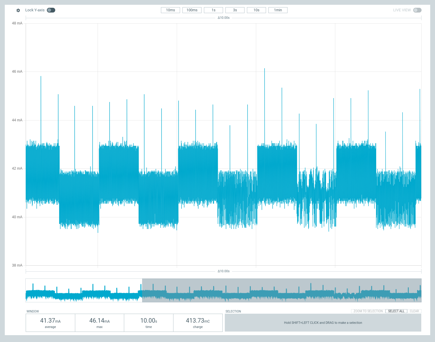
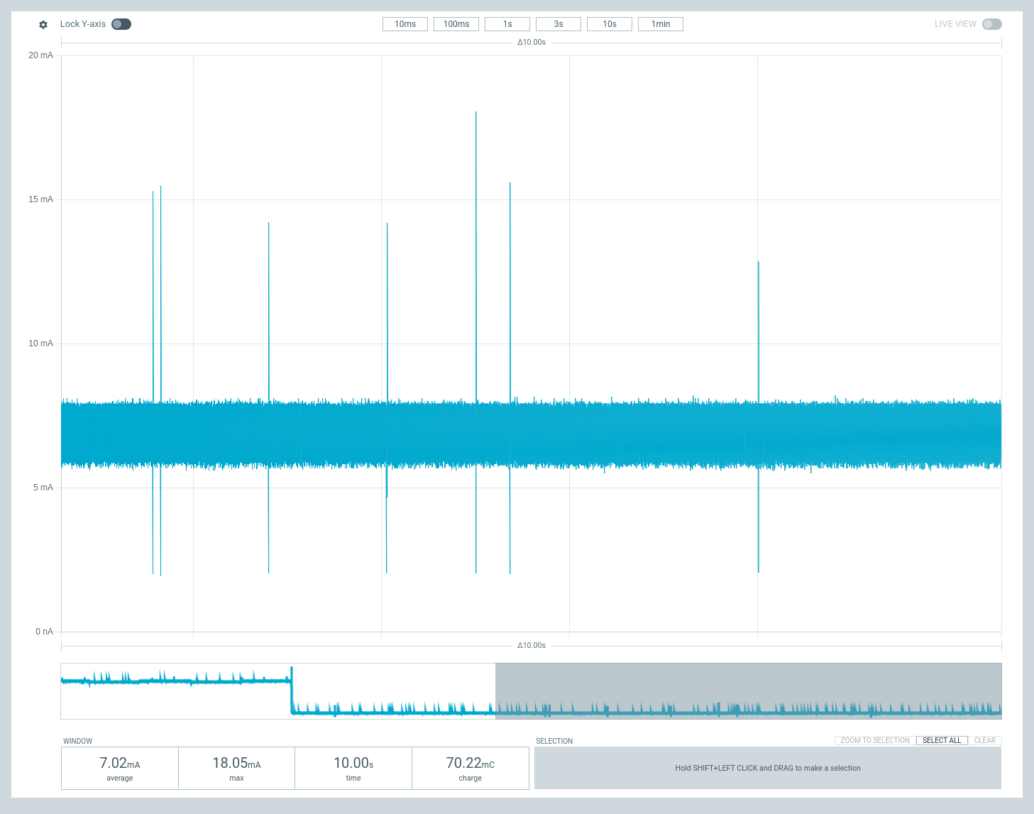
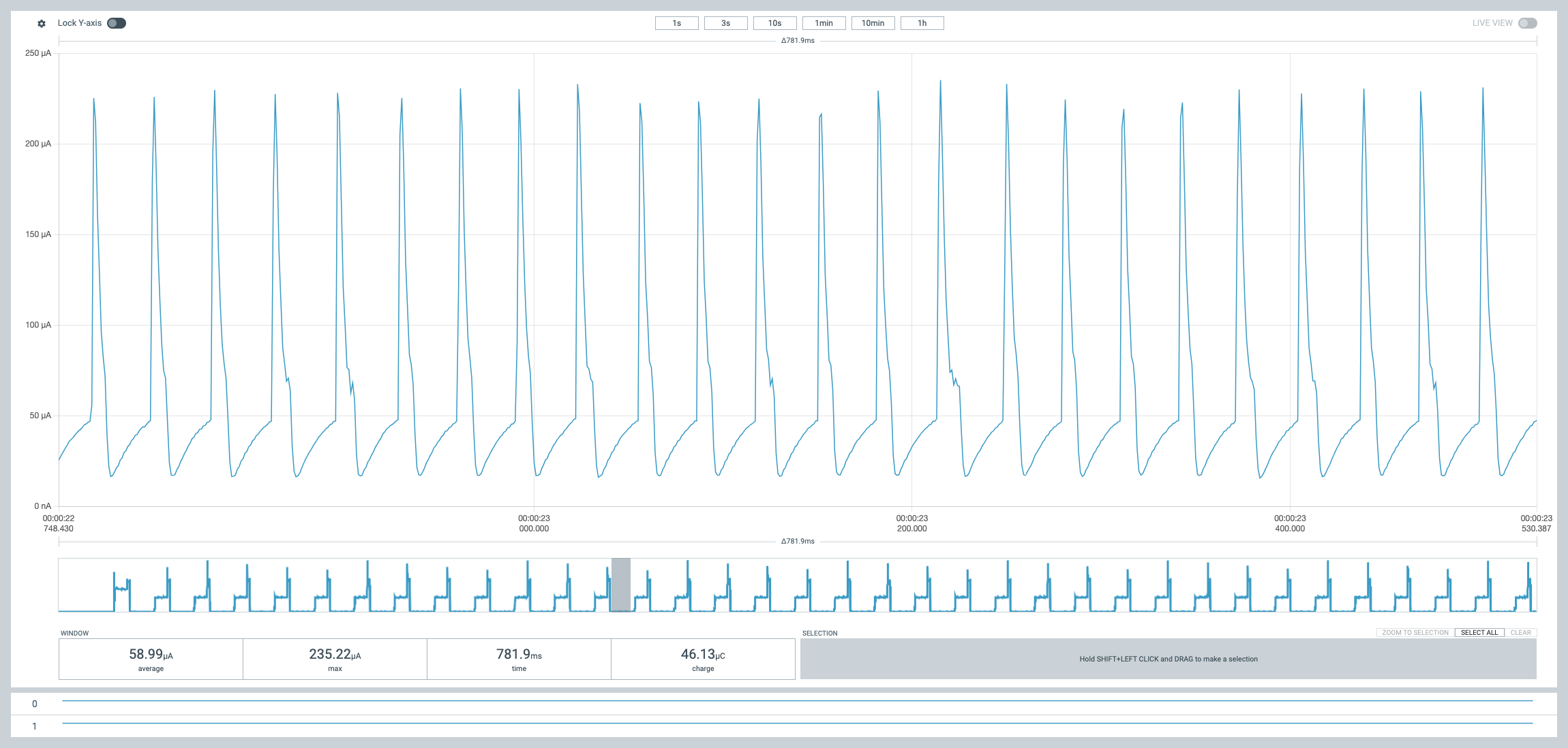
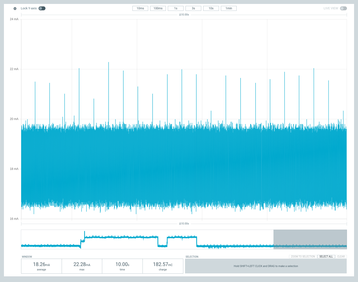
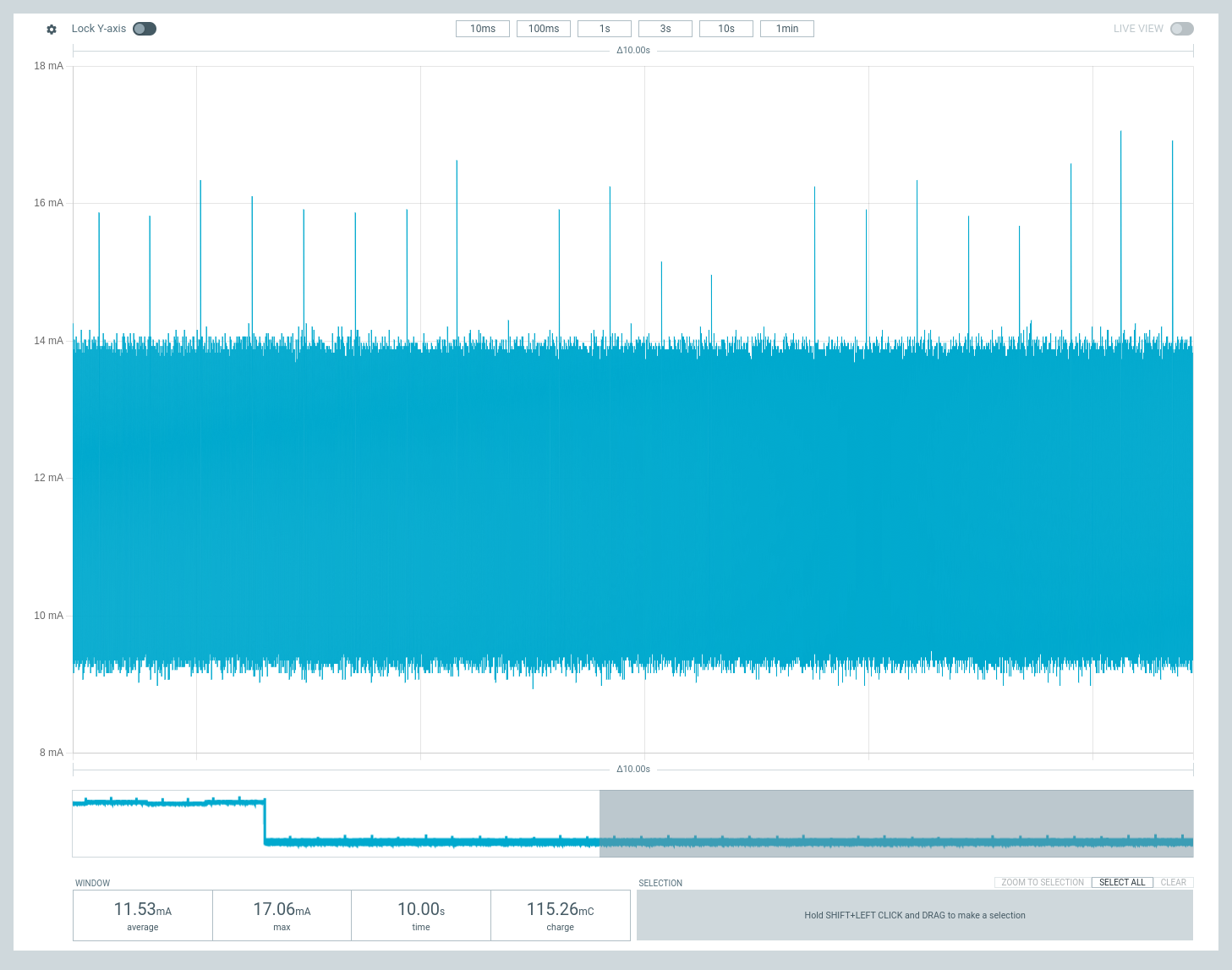
#### Low Power Measurements
Here's an overview of the reduction in power usage that you can expect from this library on the Portenta C33. The screenshots below are taken from the nRF Power Profiler application using a Nordic PPK2 while running the blink sketch on the same board.
#### Without power optimisations
#### Sleep (ADC, RGB LED, Secure Element, Wifi and Bluetooth off)
#### Deep Sleep (ADC, RGB LED, Secure Element, Wifi and Bluetooth off)
#### Sleep (ADC, RGB LED, Secure Element, Wifi and Bluetooth on)
#### Deep Sleep (ADC, RGB LED, Secure Element, Wifi and Bluetooth on)
### Portenta H7/Nicla Vison Low Power
When utilizing Mbed with STM32-based microcontrollers such as the Portenta H7 and Nicla Vision, the approach to managing sleep modes exhibits some unique characteristics. Mbed is designed to transition the board to a sleep-like state—akin to the Sleep Mode found on the Portenta C33—whenever the system is not actively processing tasks. This energy-saving feature can be activated by invoking the `board.enableSleepWhenIdle()` method within your code.
However, initiating this command doesn't guarantee automatic entry into sleep mode due to the presence of Sleep Locks. These locks act as safeguards, preventing the system from sleeping under certain conditions to ensure ongoing operations remain uninterrupted. Common peripherals, such as the USB Stack, may engage a sleep lock, effectively keeping the board awake even during periods of apparent inactivity. This behavior underscores how the effectiveness of sleep mode is closely linked to the specific operations and configurations defined in your sketch.
For those looking to fine-tune their board's energy efficiency by leveraging automatic sleep functionality, a particularly useful resource is [Alrik's example sketch](https://github.com/alrvid/Arduino_LowPowerPortentaH7/blob/main/examples/DeepSleepLockDebug_Example/DeepSleepLockDebug_Example.ino). This sketch provides a comprehensive overview of the active sleep locks, offering insights into what may be preventing the board from entering sleep mode and how to address these obstacles. By incorporating Alrik's insights, developers can more effectively manage their board's power consumption, optimizing for both performance and energy efficiency.
#### Send the board to sleep
`board.deepSleepUntilwakeupEvent()` - Sends the board into the deep sleep state, where it consumes around ~100uA and ~300uA without peripherals.
#### Waking up from GPIO
> [!NOTE]
> There is only one Wake-Up pin on the portenta H7 ``GPIO0`` on the High Density connector. You can access it on the [Arduino Portenta Breakout Board](https://store.arduino.cc/products/arduino-portenta-breakout).
#### Waking up from RTC
This feature is particularly useful when you want to set the board to wake up at specific times. To make your board wake up on an RTC alarm you simply need to call `board.setWakeupRTC()` and it will enable that functionality.
To simplify things, we have added a convenience function in `Board` called `sleepFor`. This method takes a number of hours, minutes and seconds as a parameters. For more information, check out the [DeepSleep_WakeFromRTC_H7](https://github.com/arduino-libraries/Arduino_PowerManagement/blob/main/examples/DeepSleep_WakeFromRTC_H7/DeepSleep_WakeFromRTC_H7.ino) example.
```cpp
PowerManagement manager;
Board board;
void setup() {
manager = PowerManagement();
manager.begin();
board = manager.getBoard();
board.enableWakeupFromRTC();
board.sleepFor(0, 0, 1);
board.setAllPeripheralsPower(false);
board.deepSleepUntilWakeupEvent();
}
```
### Toggle peripherals
* `board.setAllPeripheralsPower(false);` - Turn the peripherals on Portenta C33 (ADC, RGB LED, Secure Element, Wifi and Bluetooth) off.
* `board.setAllPeripheralsPower(true);` - Turns them back on. (should be called as close to the beginning of the `void setup()` method as possible.
> [!WARNING]
> This method toggles power to important system peripherals like the DRAM, Oscilllators, USB and Ethernet PHY chips. Do set this to `false` unless it's before sending the board to sleep, as it might cause undefined behaviours.